A Detector of Laser Pulses for a Wavelength of 400-1100 nm
The general mode of operation
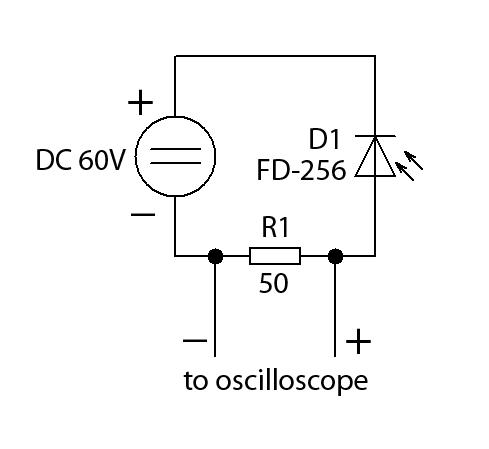
The pulse detector is based on a photodiode incorporated according to a photodiode circuit with a load resistor and an inverse power supply voltage polarity.
When a light signal hits a photodiode, charge carriers are generated inside it. Their quantity is proportional to the light signal power. These carriers are caught by the electric field created by the voltage applied to the photodiode, and an electrical current proportional to the light signal power is generated in the circuit. By measuring the load resistor voltage with an oscilloscope, it is possible to measure the shape and duration of the light signal pulses. To measure pulses the photodiode and oscilloscope time resolution should be several times less (preferably, by an order) than the duration of the measured pulses.
In our detector, we use a photodiode FD-256.
Universal laser pulse detector demo
A universal laser pulse detector in action

A universal laser pulse detector measurements

Photodiode features (the key component):
The photosensitive cell (effective) area is 1.37 mm2;
Service voltage 10 V
Spectral sensitivity range 0.4 – 1.1 µm
Maximum spectral characteristics 0.8 – 0.9 µm
Dark current, not above 5 nA
Integral current sensitivity, no less than 0.02µA/lx
Intrinsic time constant (U = 10 V), not above 10ns
The intrinsic time constant (U = 60 V), not above 2ns
As seen from the photodiode characteristics, its time resolution is 2 ns at a supply voltage of 60V. So, with its help, it will be possible to measure pulses with a duration of no more than 10 ns. While the oscilloscope should have at least 80MHz bandwidth. If its bandwidth is less, then 10 ns pulses will appear longer and with shape distortions.
To determine the required load resistor resistance you can use the ratio R*C << the measured pulse duration, where R is the resistor resistance, C is the oscilloscope input capacitance. The oscilloscope input capacitance should be specified in its specifications, but the approximate C value can be considered as 20pF (0.02nF). That is, if we measure a 10ns pulse then R*C should be several times less (preferably by an order ), but no more than 1-3. R = 1/C = 1/0.02 = 50 ohms.
Pulse detector circuit

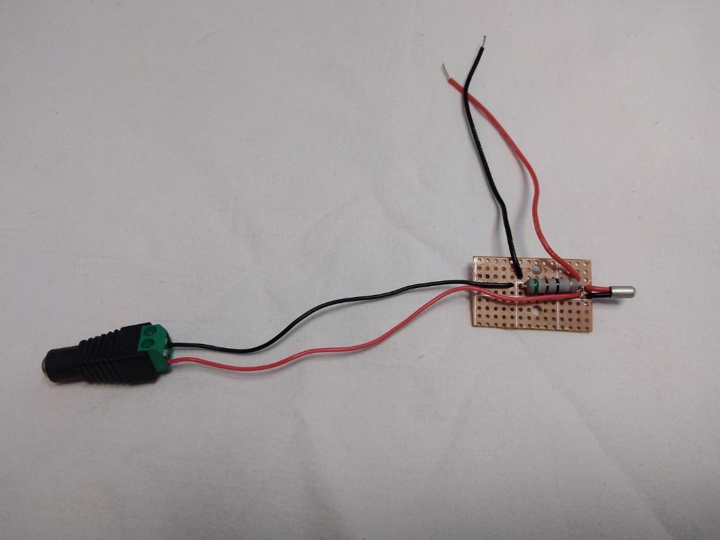
 Endurance DIY pulse detector
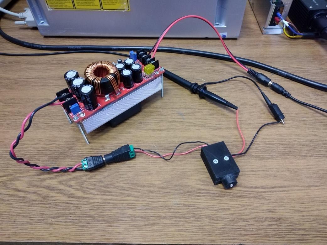
 Step DC/DC
Safety precautions when using the pulse detector
In order not to damage the photodiode it is necessary to protect it from direct laser radiation. Only unfocused scattered laser radiation is safe for the photodiode. To scatter the laser radiation it is necessary to install a light signal attenuator between the laser and the photodiode. One or more sheets of white paper or a piece of frosted glass can be used as a light attenuator. It is also possible to place the photodiode not in the center of the laser spot but at its edge. In addition to it, you can also install a special mirror between the laser and the light attenuators to reflect most of the laser beam energy.


