Allows changing laser power "on-fly" while you operate the laser.
A great tool for all CNC users.
Recommended for all Shark owners.
The PWM signal adjuster is designed to dynamically adjust the power, focus and operation of diode, CO2 and DPSS lasers, and to convert the PWM output signal of the CNC board controller to the TTL level.
Electrical specifications:
- Power supply voltage : +12В +-10%
- Power consumption: 100мА +- 10%
- Output amplitude
- PWM Out (X1, X2 1-2) : 0В - 5В +- 10%
- PWM Out (X1, X2 1-2) : not greater than 50 mА
- Output signal amplitude
- Open collector (X1, X2 2-3) : 0В - 24V +- 10%
- Output Open collector (X1, X2 2-3) : not greater than 100 mА
- Output frequency (mode 1, 2): 500 Hz
- Output frequency ( mode 0): equals the CNC controller signal frequency
- Pulse duration for mirrors adjustment
- СО2 laser (mode 3): 5 ms – 100 ms
- Output signal inversion
- relative to the input signal: yes (X3 1-2)
- PWM duty cycle (Mode 1, 2): 0-100% +-10%
- PWM duty cycle (Mode 0): equals the CNC controller duty cycle
- Input signal amplitude (In1): 0-24 +- 10%
- Input 1 minumum voltage for laser activation: 1.5V +-10%
- Input signal amplitude ( In2): 0-12V +-10%
- Input 2 minimum voltage for laser activation: 3.5V +-10%
- Input signal frequency (Mode 0): up to 5khz
- External controls and indications
- Pins 1-2(XT3) (PWM+ PWM-): to laser PWM + PWM-
- Pins 3-4(XT2) (In2+ In2-): to CNC controller PWM + PWM-
- Pins 5-6(XT1) (In1+ In2-): to CNC controller PWM + PWM-
- SW1: operating mode selection
- Status LED: Status indicator
- Duty cycle ADJ: PWM duty cycle adjustment
- Duty cycle: duty cycle х10%
- Power 12V: to 12V DC power supply unit
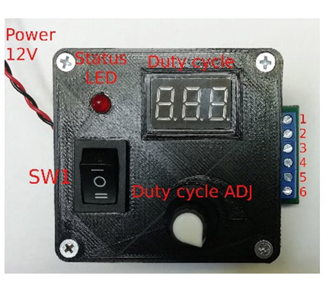
Fig. 1.
Mode switches on the control board
There are three switches X1, X2, X3 on the control board of the PWM signal dynamic adjuster. Mode switching is done by rearrangement of jumpers on pins 1,2,3. Each switch makes it possible to select two positions:
- Position 1 – jumper on 1-2 pins of X1, X2, X3 switches
- Position 2 – jumper on 2-3 pins of X1, X2, X3 switches
It is not permitted to use the PWM signal dynamic adjuster with other jumper positions, unlike those specified in this manual or without them.
The inversion mode of the output signal relative to the input signal is set by the X3 switch.
If the jumper on the Х3 switch is in position 1 (Fig. 2) the output signal (1-2 pins, fig. 1) will be inverted relative to the input signal (3-4 or 5-6 pins, fig. 1).

Fig. 2.
Non-inversion mode
If the jumper on the Х3 switch is in position 2 (Fig. 3) the output signal (1-2 pins, Fig. 1) will have the same polarity as the input signal ( 3-4 or 5-6 pins, Fig. 1).
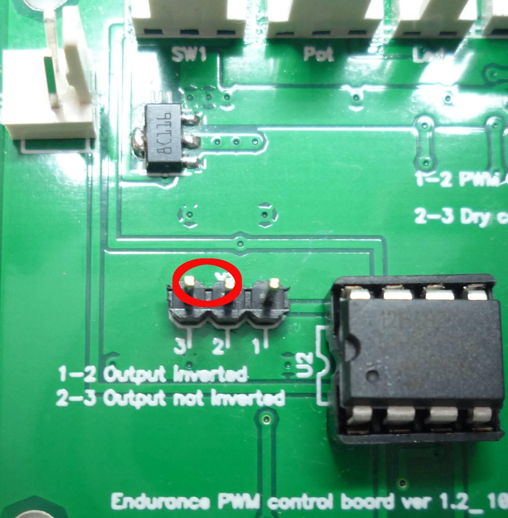
Fig. 3.
Output stage with an emitter repeater. If the jumpers on Х2 and Х1 switches are in 1-2 positions (Fig. 4) the output of the dynamic PWM adjuster is embodied according to the circuit of the emitter repeater. 1-2 pins (XT3) (PWM+ PWM-). For visual clarity, the output stage, in this case, is shown in Fig. 5.

Fig. 4.
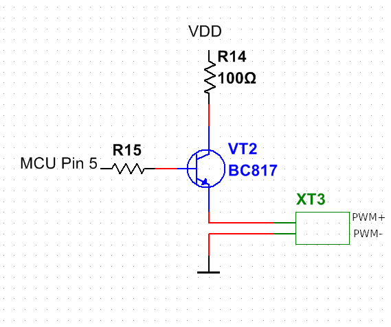
Fig. 5.
Open collector output. If the jumpers on the Х2 and Х1 switches are in 2-3 positions (Fig. 6) the output of the dynamic PWM adjuster is embodied according to the open collector circuit. Pins 1-2(XT3) (PWM+PWM-). For visual clarity, the output stage, in this case, is shown in Fig. 7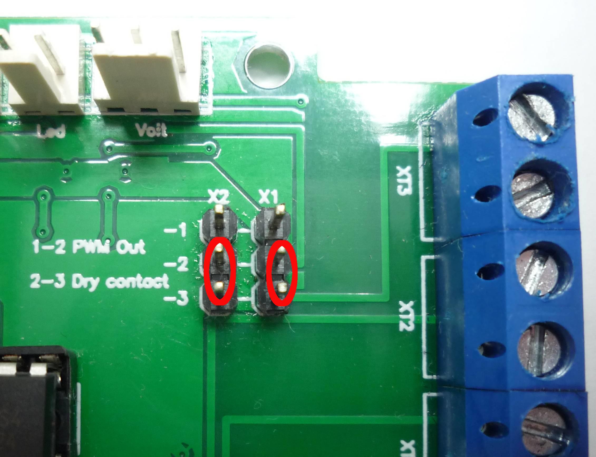
Fig. 6.
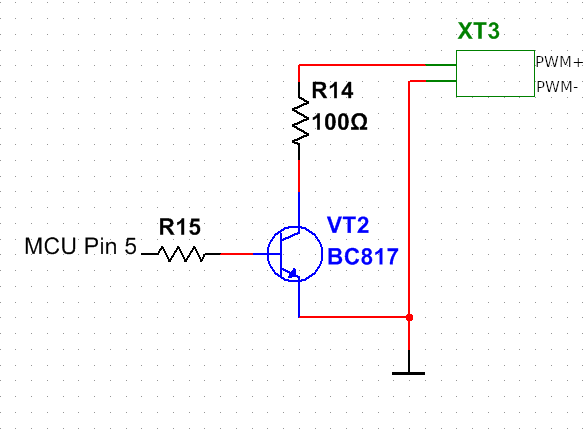
Fig. 7.
Operating modes of the dynamic PWM signal adjuster
An operating mode is set with the mode switch SW1. There are three operating modes:
Mode I: Manual laser power adjustment. The laser power is independent of the signals on pins 3-4 or 5-6. The Status LED indicator is constantly lit. The Duty cycle ADJ knob sets up a duty cycle from 0 to 100%. The Duty cycle indicator monitors the duty cycle values. The indicator readings are multiplied by 10%. For example, if the indicator reads 2.10 it means that the PWM duty cycle is 21% (2.10 х 10% = 21%).
It is possible to use this mode for laser focusing if the duty cycle values are set in the range of 0.1 – 0.5.
Mode 0: Conversion of the input signals on 3-4 or 5-6 pins to the TTL 0-5V level. The Status LED is lit when the signal level on 3-4 or 5-6 pins is high (for more details go to the Electrical specifications
of this instruction). The Duty cycle ADJ knob and readings of the Duty cycle indicator do not affect the operation of the device. If your CNC controller outputs a signal other than TTL, and the laser requires for its operation a signal in the range of 0-5V, then, in this mode, the CNC controller output voltage is converted to the TTL level. For the correct work of the device in this mode, the output signal frequency must not go beyond 5khz.
Mode II: Dynamic laser adjustment. In this mode, it is possible to change the laser power in the course of the CNC program operation. The Status LED is lit when the signal level on 3-4 or 5-6 pins is high (for more details go to the Electrical specifications of this instruction). The Duty cycle ADJ knob sets up a duty cycle in the range from 0 to 100%. The duty cycle readings are monitored by the Duty cycle indicator. The readings of the indicator are multiplied by 10%. For the correct operation of the device in this mode, it is necessary that the CNC program (g-code) generates a signal either with 0% or 100% PWM duty cycle level. Any intermediate values of the PWM duty cycle will result in incorrect operation of the device.
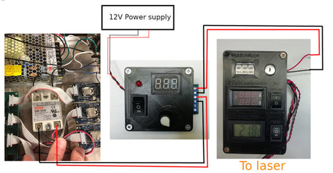
How to connect the device
How to use the dynamic PWM signal adjuster to connect the ignition unit of the CO2 laser tube
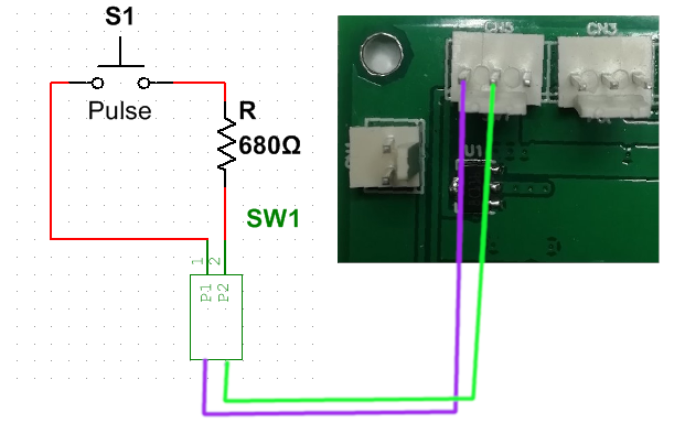
If we replace the three-position switch SW1 in the dynamic PWM signal adjuster with the button shown in the diagram (Fig. 8), we’ll make it possible to generate a pulse with an adjustable duration from 5ms to 100ms. This mode is suitable for adjusting mirrors on the laser beam path from the laser tube exit to the nozzle.
Fig. 8.
Adaptation of the dynamic PWM adjuster for connection to the CO2 ignition unit and adjustment of the mirrors is shown in Fig. 9.
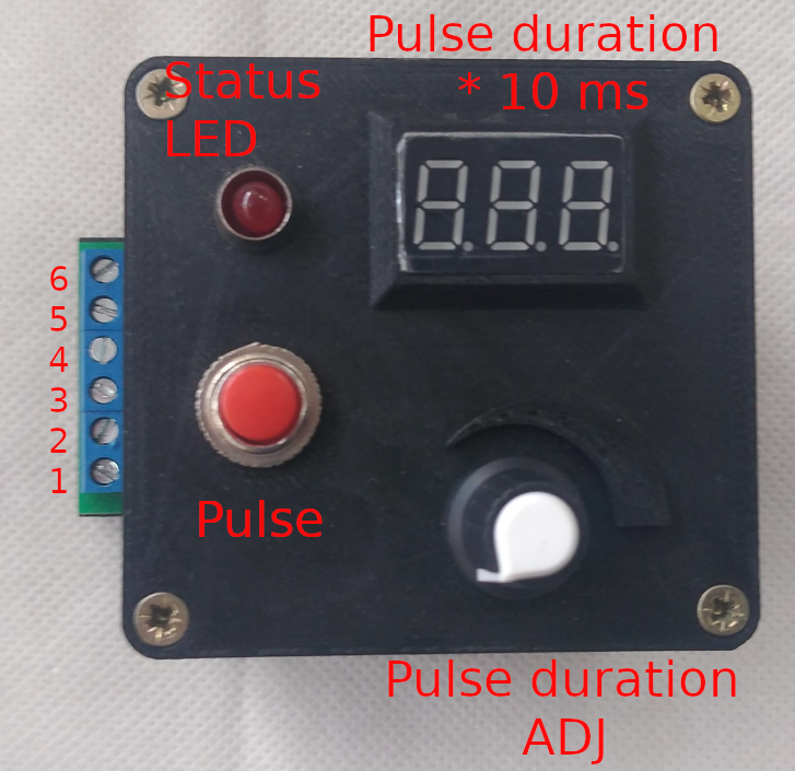
Fig. 9.
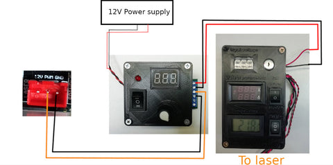
The output of most CNC controllers differs from TTL 5V, while most ignition units require the control signal from the CNC controller to be not higher than 5V. In this case, 3-4, 5-6 pins are used for connection to the CNC controller according to the Electrical specifications of this instruction. 1-2 pins of the dynamic PWM adjuster are connected to the H/L - GND pin of the ignition unit according to the ignition unit manual. The Pulse button when pressed generates a pulse of 5 ms to 100 ms duration. The Pulse duration ADJ knob sets the pulse duration, its current readings are shown on the Pulse duration display. The pulse duration readings are multiplied by 10 ms. The Status LED indicator is lit when the PWM input (3-4 or 5-6 pins) signal level exceeds the minimum voltage to activate the laser (voltage values are given in the Electrical specifications of this instruction) or when the Pulse button is pressed.
Adjustment of the switches on the dynamic PWM board is done according to the instruction section Mode switch setting on the control board and the requirements of your ignition unit manual.
An example of the dynamic PWM adjuster connection and usage
Example 1. Dynamic adjustment of the PWM signal duty cycle.
Let’s take as an example connection to the Shark CNC (Fig. 10). At the working areas of the laser, the G-code is generated in such a way that the laser starts operating always with 100% power. With the Duty cycle ADJ knob, it is possible to change the laser power during the operation process of the CNC Shark. Mode II is used for operation.
Fig. 10.
Example 2. Conversion of the CNC controller output signal with an amplitude of 12V-24V to the TTL 5V. If you need to convert the output signal level of your CNC controller (most MACH3 controllers and almost all 3D printer motion controllers) to the TTL 5V, connect the adjuster according to the general wiring diagram (Fig. 11.) and select Mode 0 using the SW1. Use In1 or In2 inputs to connect the dynamic PWM according to the Electrical specifications of this instruction.
Example 3. Changing the PWM duty cycle during operation without changing the control program or the g-code file.
Use the general wiring diagram (Fig. 11). Select the dynamic PWM connection input In1 or In 2 according to the Electrical specifications of this instruction. Select Mode II with the SW1. In this case, the control program or g-code file will turn on the laser with 100% power only and turn it off completely (0% power). Laser power adjusting/setting is done dynamically (during operation of the control program or before its start) with the Duty cycle ADJ knob. The current power value is equal to the reading on the Duty Cycle display of the dynamic PWM adjuster multiplied by 10%.
Fig. 11.
Example 4. PWM signal inversion.
Some CNC controllers, as a result of their hardware implementation, generate an inverted PWM signal (e.g. the Snapmaker controller). For the correct operation, Endurance lasers and many Chinese lasers require direct polarity of the PWM signal: when the PWM signal is high the laser is on, when ths PWM signalis low the laser is off. Let’s take as an example connection of the dynamic PWM signal adjuster in the wiring diagram with an inverted PWM signal (Fig. 12). The position of the dynamic PWM board X3 switch is shown in Fig. 2, and the position of the X2 and X1 switches is as in Fig. 4. Operation Mode 0 is selected with the SW1 switch.
Fig. 12.
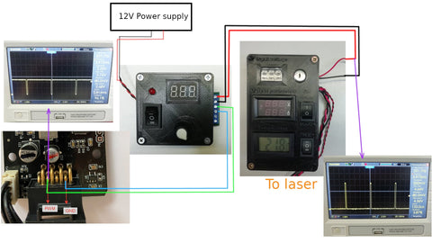
Example 5. Connection of the CO2 laser ignition unit to the controller based on the GRBL firmware via the dynamic PWM signal adjuster.
Let’s take as an example connection of the widely-used CNC Shield v3.0 board based on the GRBL firmware to the equally widely-used Cloudray 40W CO2 Power Supply ignition unit via the dynamic PWM adjuster. (Fig. 13)
The position of the switches on the dynamic PWM adjuster board is shown in Figs. 3 and 6.
- X1: 2-3
- X2: 2-3
- X3: 2-3
The Pulse duration ADJ knob (Fig. 9) adjusts the pulse duration from 5 ms to 100 ms for the mirror setting. A single pulse of the set duration is formed by pressing the Pulse button (Fig. 9).
Fig. 13.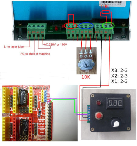
At the working areas of the laser, the G-code is generated in such a way that the laser starts operating always with 100% power. The laser power is controlled by a 10K potentiometer connected to the corresponding ignition unit (Fig. 13).
The coolant flow sensor is blocked. If necessary, remove the jumper (G-P pins) Fig. 13 from the ignition unit and connect it to the flow sensor.
Technical implementation:
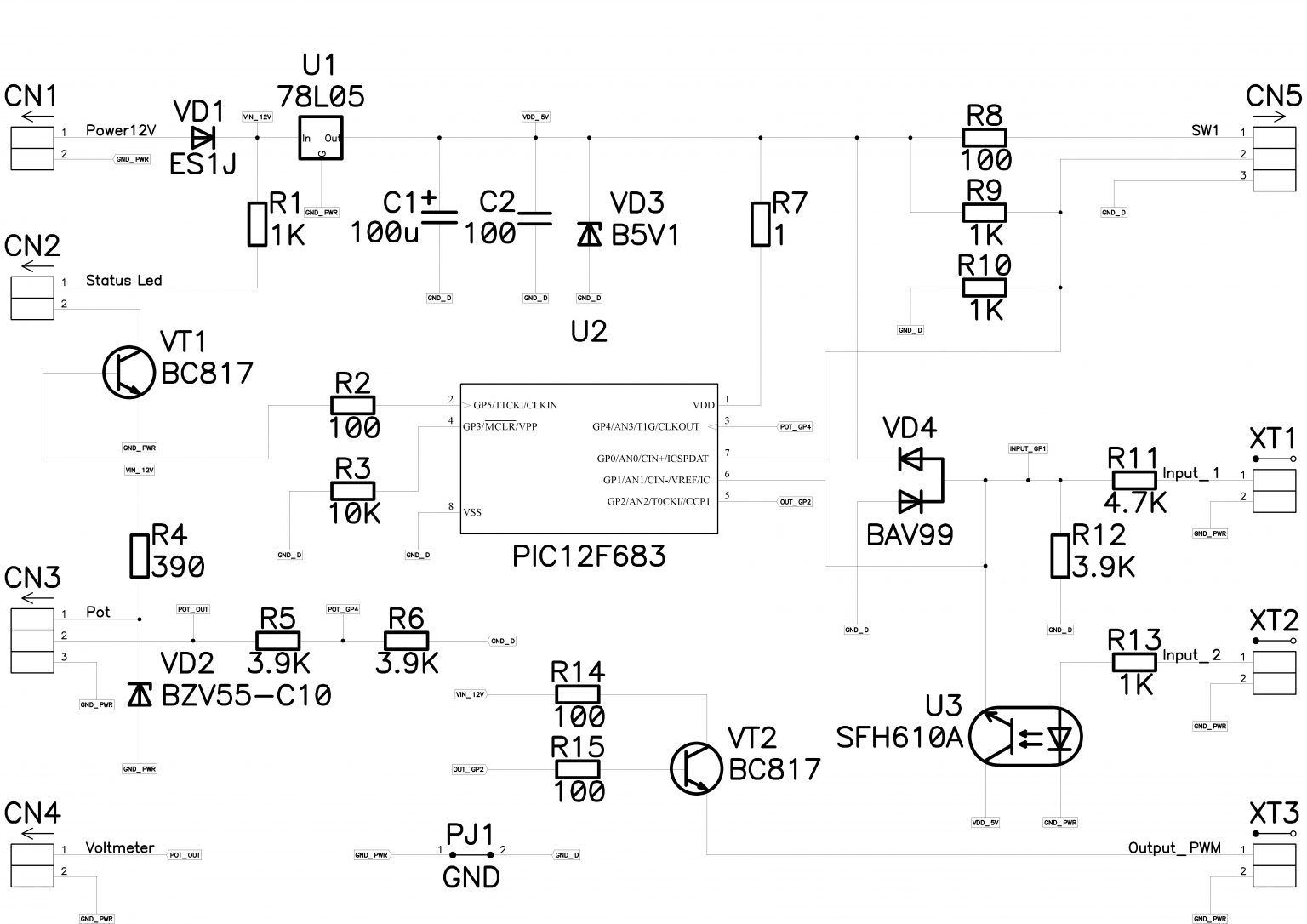
The PWM signal adjuster is assembled on the basis of the Microchip PIC12F683 controller.
To operate in mode I, 0, II, a hardware timer, a comparator, and an analog-digital converter of the controller are used, which increases the speed and accuracy of the signal processing by the controller. The PWM signal adjuster is protected against the reverse polarity of the input signal and 12V power supply voltage.
Warning:
To avoid damage to the device, CNC controller, or laser, don’t exceed the values specified in the Electrical specifications of the instruction by more than 20%.
Laser radiation is hazardous to vision. Wear personal eye protection. To avoid possible intoxication by the combustion products during laser processing, use the laser in well-ventilated rooms with forced air ventilation.
To prevent fire, do not leave the running laser unattended.
Mode 1 - 100% signal from the controller; turn the knob; change the power as needed.
Mode 0 - Off
Mode 2 - This is the manual mode (we adjust the power with the handle) as on the stand. There is nothing to enter at the entrance.
The wires that are marked IN are connected to the CNC controller.
Wires that connect OUT to a TTL laser
Engraving on PLA plastics with dynamic PWM box
Laser bonding using a DPSS 10 watt laser and a dynamic PWM box.
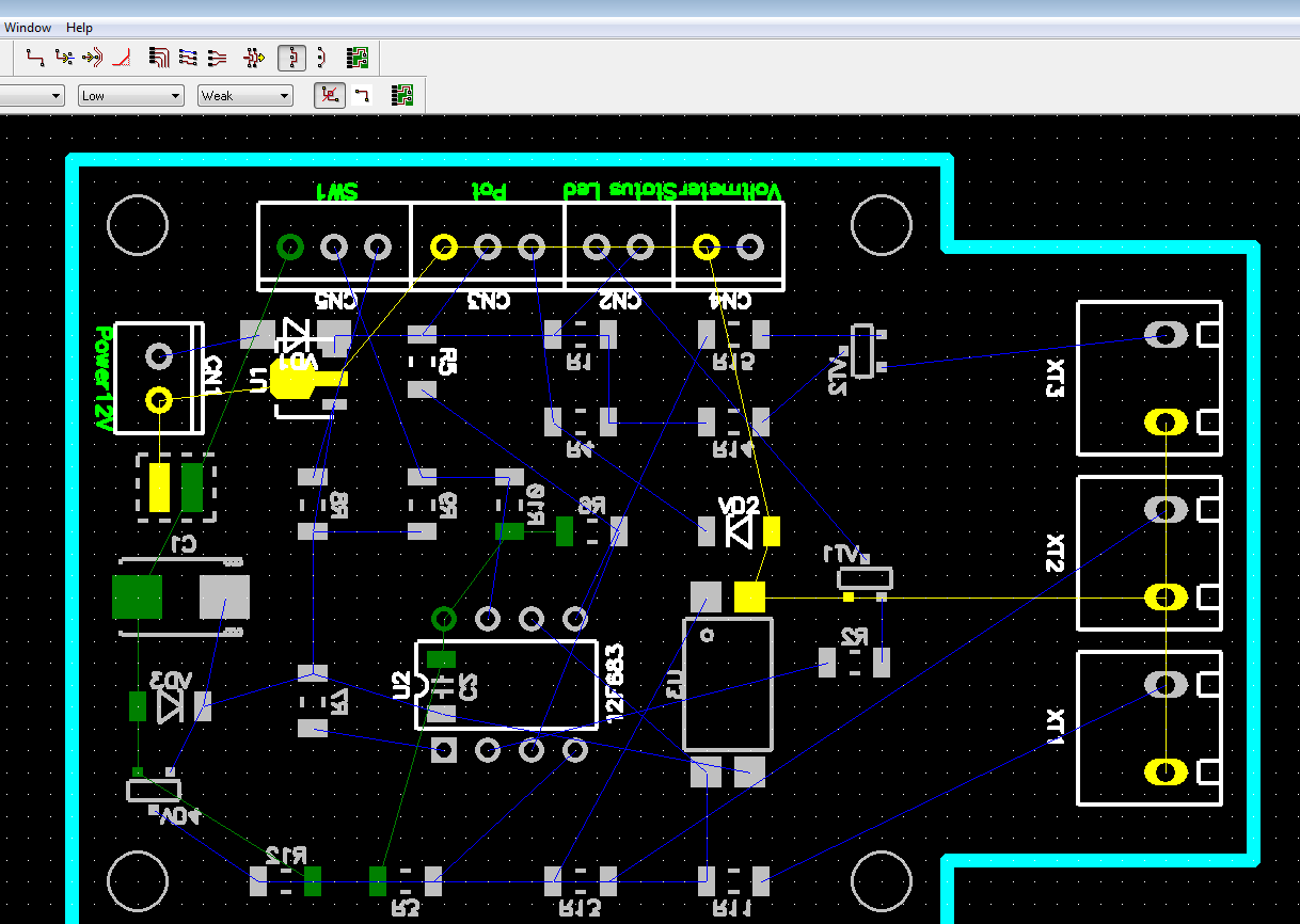
PCB design and the schematic